CAD and CFD
Jet Engine Design and Optimisation
A 19-part jet engine modelled in Solid Edge, then tested in ANSYS fluid simulation to improve its efficiency by reshaping and re-angling the turbine blades.
Mission profile
- Parts
- 19 in one assembly
- CAD
- Solid Edge
- Simulation
- ANSYS fluid simulation
- Turbine stages
- 5 air + 5 petrol
- Design variables
- Blade shape and angle
- Objective
- Higher efficiency
What this actually is
A jet engine is a machine for moving air. Air is drawn in at the front, squeezed by rows of spinning blades, mixed with fuel and burned, then expanded through more blades at the back. Those rear blades take just enough energy from the hot gas to drive the front, and whatever is left leaves the exhaust as thrust.
Almost all of that work happens on the surface of a blade. The shape of its profile and the angle it meets the flow decide how cleanly the air is turned. Get the angle slightly wrong and the flow separates from the surface, creating losses and turbulence instead of useful work. Small geometric changes, repeated across every blade in every stage, add up to a large difference in efficiency.
That is why turbine blades are designed with fluid simulation rather than by eye. Computational fluid dynamics shows the pressure and velocity of the flow around each blade, so different geometries can be compared on screen long before anything is machined.
Overview
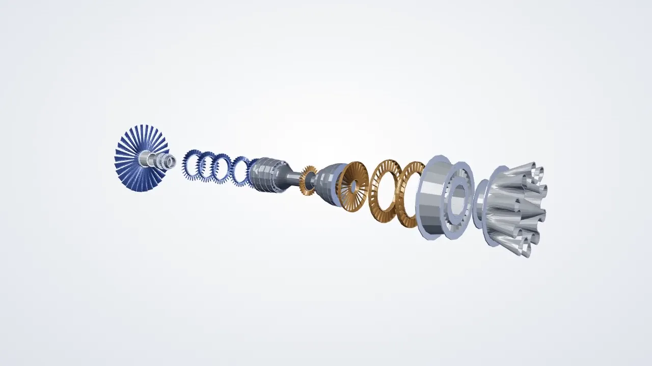
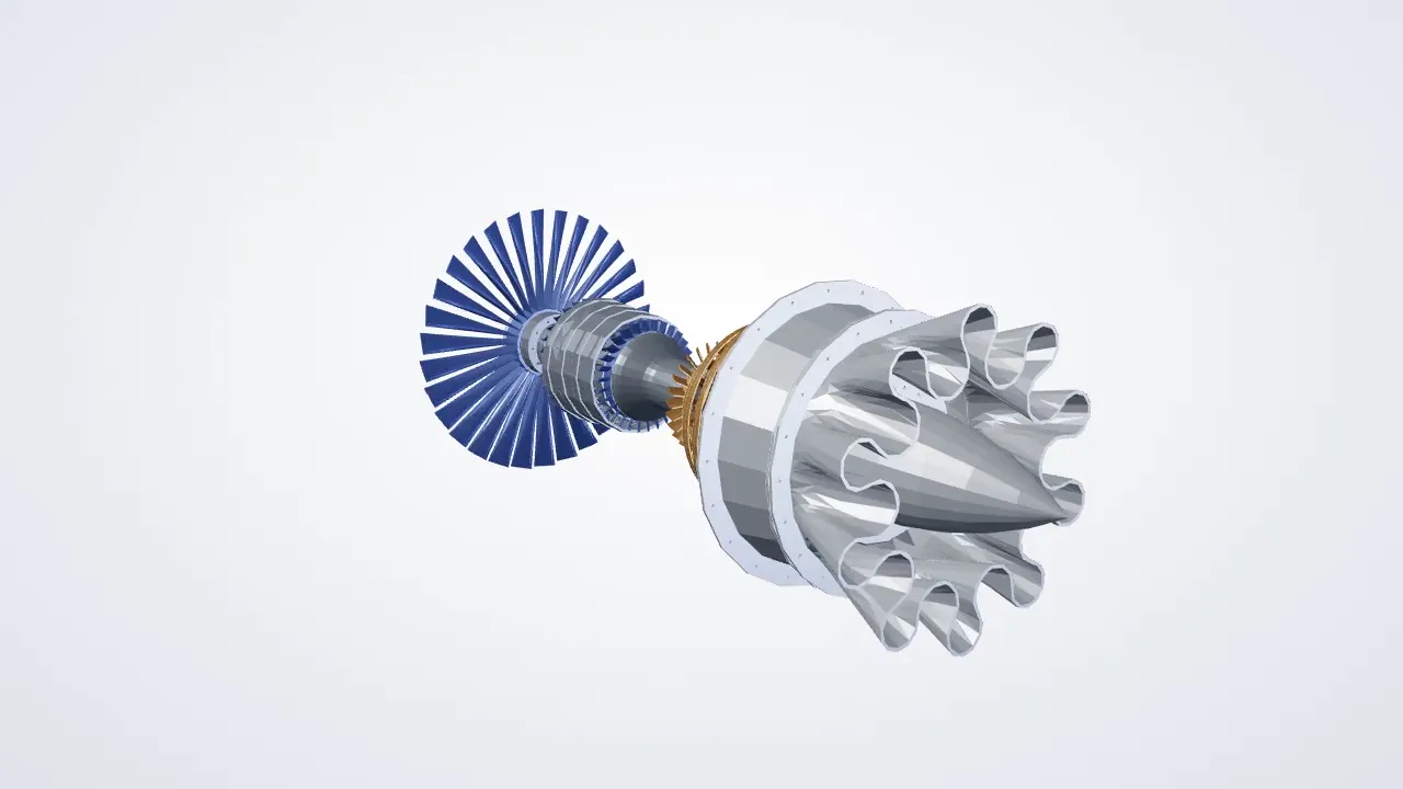
I modelled the full engine in Solid Edge as a 19-part assembly: nose cone, primary turbine bushing, bearing, central and rear mounting shafts, rear case, exhaust case and end cone, the primary turbine, five air turbine stages and five petrol turbine stages, all aligned on the shaft axis.
With the geometry built, I used ANSYS fluid simulation to study how air moves through the engine and how efficiently the stages work. I then changed the shape and the angle of the turbine blades and re-ran the simulation to compare designs, keeping the geometry that turned the flow more cleanly. The exploded-view animation at the top of this page is rendered directly from the CAD files.
Role
Design and simulation engineer
Built the CAD model and ran the fluid simulations.
Key requirements
- Complete, aligned 19-part assembly
- Fluid simulation of the flow path
- Comparable blade design variants
- Efficiency as the deciding measure
Approach
- Model each part in Solid Edge
- Assemble the engine on the mounting shafts
- Set up the fluid simulation in ANSYS
- Vary turbine blade shape and angle
- Compare efficiency and refine the design


Engineering notes
Tools
- Solid Edge
- ANSYS
- Fluid simulation (CFD)
- Assembly design
Deliverables
Full 19-part CAD assembly, fluid simulation studies of blade variants and an exploded-view animation.